
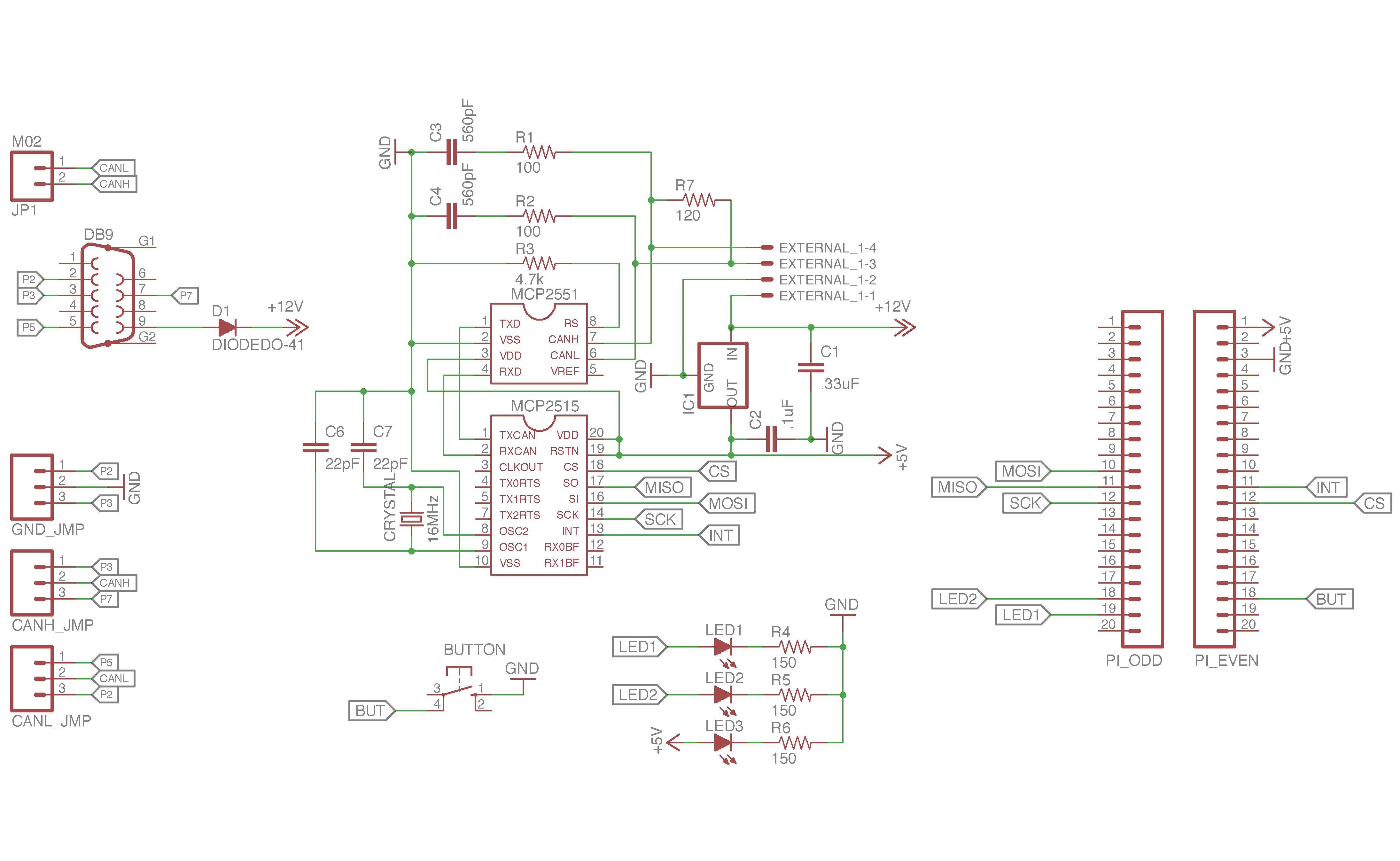
This spring semester I worked with a friend to build an updated Raspberry Pi Zero CAN Shield for our ECE4180 final class project. Building off of my CAN Shield project from last summer, we were able to fit a standard DB9 connector onto the board without compromising the board dimensions. We wanted to add this connector since it is a common standard for CAN Bus connectivity, and by using a smaller CAN controller chip package as well as removing a duplicate connector, we were able to make it happen. More information about this project can be found in our writeup here.


Revision 2
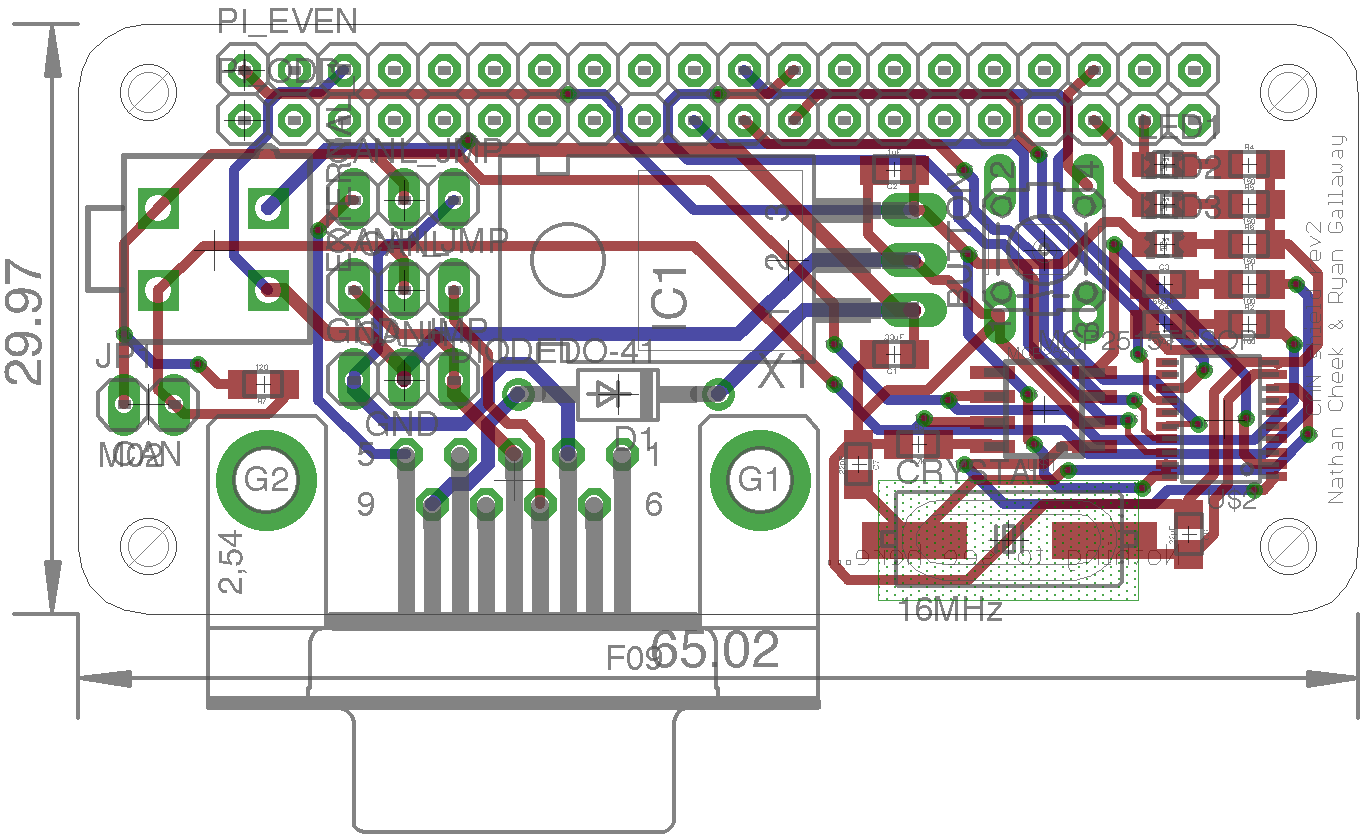
The 2-layer PCB was designed in EAGLE. Linked here are the schematic, board, and Gerber files. I opted to start the board design from scratch instead of using the previous revision as a starting point. I have found that starting board layouts from scratch allows me to better evaluate where components should go without being tied to the design decisions made for previous revisions. This is especially important when major changes are being made, such as the additions of large components.


Revision 3
In the design of revision 2, I ran into an issue with the CAN Bus termination resistor. In the board layout process, I was unable to find an easily accessible location for the resistor so I left it nestled between the Molex Minifit Junior and DB9 connectors. While testing the board with our vehicles, I needed to remove this termination resistor. Since this proved to be somewhat difficult, I decided to fix the position of this resistor with a third revision. I also removed the Minifit Junior connector and replaced it with the more commonly used standard DC barrel jack connector.
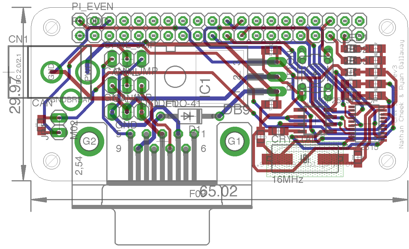
While I have not manufactured revision 3, the placement of the termination resistor is much more accessible and the barrel jack should be more useful than the Minifit connector to most people. The board file and schematic file are available here.