
In 2016 I put together an 10x10 RGB LED matrix using individually addressable APA-106 8mm LEDs. These lights are drop in replacements for the expensive NeoPixels sold by Adafruit, but instead of $1 per LED, they cost around $.20 each. I purchased several lots of 100 on AliExpress. The benefit to this type of RGB LED is that a large number of LEDs can be controlled with a single pin on a microcontroller. Controlling LEDs by directly switching them individually quickly becomes a cumbersome task, but by placing an integrated chip in each bulb, hundreds of lights can be controlled digitally.
It was easy to get these LEDs working by following Adafruit’s Neopixel Guide. They have made an extremely useful Arduino Library. I started off by testing a few LEDs with an Arduino Nano.


To hold the LEDs in place I designed a simple cutout in AutoCAD. I used Georgia Tech’s Invention Studio to laser cut a sheet of black acrylic into the cutout design.

I chose the density of the matrix to take advantage of the length of the pins on each LED. Each pin could be splayed out in a different direction, overlapping with one pin from another LED. I could then solder each pair together, making the soldering and wiring process easier and more efficient. In each row, the data-out pin is soldered to the data-in pin on the next LED. At the end of the row, the data pin wraps down to the next row. This does make addressing individual LEDs a bit more tricky, but is fixable in software with a mapping function. In between each row is a wire carrying either 5V or 0V/gnd to power the lights.


In the following pictures you can see how the wires running between each row alternate between 5V and 0V/gnd. This means all of the LEDs are wired in parallel. Each of the LEDs inside each bulb are rated to pull up to 20mA. This means that the power supply should be able to handle 20mA/LED * 3 LEDs/bulb * 100 bulbs or 6A of current. The portable USB charger that I used here is only rated to output 2.1A which meant it was not a good fit for powering all 300 LEDs at once.


After soldering all the LEDs together, I used hot glue to attach them to the acrylic cutout. To meet the 6A power requirement, I purchased a Mean Well 5VDC 6A power supply online. For a while the control circuitry was just located on a breadboard, but I designed a more permanent control board with a few buttons and an expansion port. The schematic file is available here and the board file here.
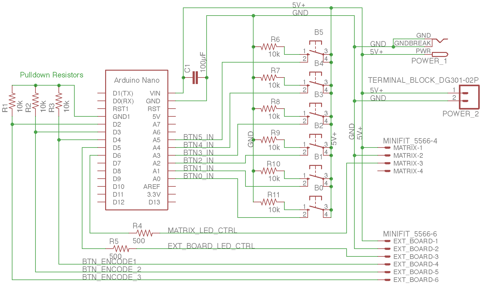
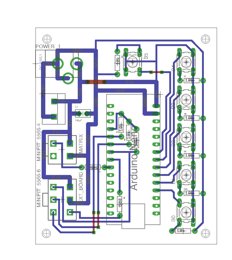
On this board I used an Arduino Nano to control the LEDs. In the future I might upgrade this project to use a Teensy LC board. The faster clock speed and extra RAM would allow it to generate more complex displays. Currently I have not developed any noteworthy patterns for the matrix to display. Right now it runs mostly Adafruit example code, along with a few patterns I quickly put together. The following is some code I wrote to set pixels using an XY coordinate system.
/*
Single pixel number
Corrects for changing direction of rows
*/
void setPixel(int pixelIn, uint32_t color) {
  int pixelOut = pixelIn;
  int row = pixelIn / 10;
  int column = pixelIn - (row * 10);
  if (row % 2 == 0) { //Even pixel
    pixelOut = row * 10;
    pixelOut += 9 - column;
  }
  strip.setPixelColor(pixelOut, color);
}

/*
X-Y coordinate system (0-9, 0-9)
Corrects for changing direction of rows
*/
void setPixel(int pixelInX, int pixelInY, uint32_t color) {
  setPixel(pixelInX * 10 + pixelInY, color);
}

