
Ever since creating my original LED Matrix, I knew there were ways to make it better. The most obvious upgrade was to fit it on a printed circuit board, but my work on this PCB design stalled as I was busy with other things. In Summer 2018 I began working on this project again, finishing the design and manufacturing a few boards as a proof of concept.
Requirements
I set out on this design with a number of requirements in mind.
First, I wanted the ability to connect multiple boards together into a larger daisy-chained display. The boards would need to fit together in such a way that the spacing between LEDs of different boards would be the same as the spacing between LEDs on the same board. That way multiple displays could be seamlessly transformed into a larger display.

While I wanted to have a PCB the size of my original LED Matrix, the cost was prohibitive. For a while now, multiple Chinese board fabs have offered 10x 2-layer PCBs up to 100x100mm in size for $5, but the price quickly goes up if those dimensions are exceeded. Instead of making one large board, I realized it might work just as well to have smaller boards that could connect to each other.
I looked at the different PCB soldermask colors available and realized black would look best no matter what colors the LEDs were displaying. At the time, selecting a non-green soldermask meant an extra $15 charge per design from my manufacturer, but I was sure it was worth it.
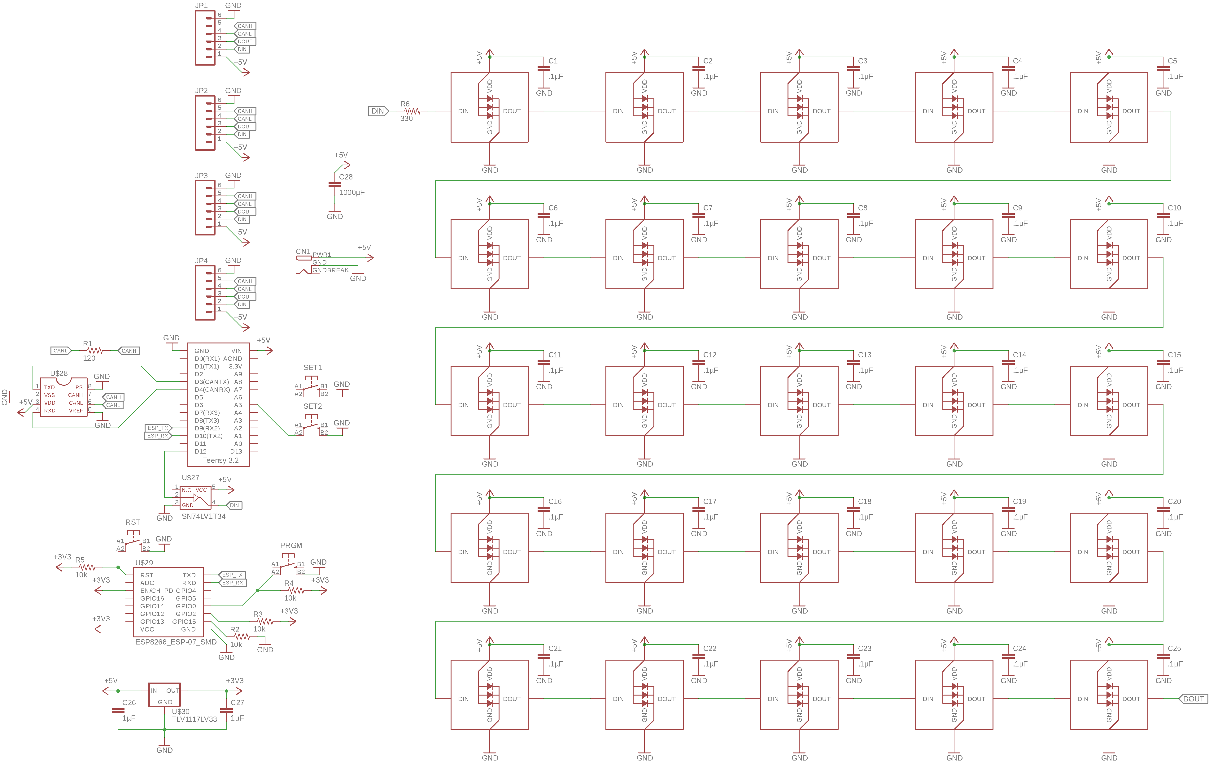
In order to interface with surrounding boards, the design would need a connector on each of the four sides. The LEDs on each board would be daisy chained and multiple boards could be daisy chained as well, but the input and output sides of each board would change depending on each board’s position in a matrix layout. This meant that each connector needed to expose power, ground, data-in, and data-out. Then, depending on each board’s location in the matrix, the correct connectors could be soldered.

I was hoping to use board-to-board connectors that would allow boards to fit right up against each other. This would allow a large screen to be easily assembled out of the small boards as seen below.
Since data-in and data-out would be exposed on each connector, I would likely just cut whichever data pin was not needed on each connector. Otherwise, a loop in the daisy chain would be created which would cause unwanted effects.

Before choosing connectors, I needed to determine how much current I would be putting through them. I settled on a 6A rating. Each LED can pull up to 20mA, and since there are three LEDs (red, green, and blue) in each bulb, each set of 100 LEDs can pull up to 6A. At full brightness, the LEDs are quite bright so I wouldn’t expect to be running at the 60mA per bulb maximum. However, I would likely want to power more than 100 LEDs off a single power supply, so 6A seemed like a reasonable compromise.
This system would need a microcontroller to control the LEDs. One option was to use a separate board which would provide power and data to the matrix. A cheaper option was to embed the controller into the LED board design. If I could create a single design that integrated the LEDs and control hardware then I would only need to manufacture a single board design. I didn’t want a controller on each board though, so it would need to be possible to install the controller hardware on a single board, which could then send the data signal throughout the daisy-chain matrix.
With a microcontroller embedded within the first board, only 5V power and ground would need to be supplied to the array of boards.

There was the chance I’d want to connect a lot of these boards up to make a very large display. As you add more LEDs onto the daisy chain though, it takes longer to send the commands necessary to update all of the LEDs. This results in a lowered frame rate. Each LED also requires some amount of memory in the controller. This means there is a limit to how many LEDs can be controlled by a single controller. To get around this, I wanted a way to set up multiple controllers in sync with each other.
Finally, I wanted some way of controlling the LEDs remotely. Perhaps this would eventually be through a web interface or an app, but the board needed to support this capability.
List of Design Requirements
- Ability to daisy chain boards to create large seamless displays
- Each board no larger than 100 x 100 mm
- Black soldermask
- Board-to-board connectors
- 6A current rating (connectors and PCB traces)
- Single board design regardless of location in array or whether controller is onboard
- Communication channel between controllers
- Some way of controlling remotely
Design
As I began the design, there were still a few questions that needed answering. What LED spacing would I use? What connectors? What controller would I use and which communications protocols would I add support for?
I noticed that if I set the board size to 100 x 100 mm, 5 rows and 5 columns of the 8mm LEDs would fit quite nicely. This gave 20mm center-to-center between each LED which approximated the spacing of my previous LED matrix project.
I spent quite a bit of time researching board-to-board connectors. Unfortunately, I was unable to find a suitable connector system. In most cases, either the current rating was not high enough or the dimensions of the connectors would cause them to interfere with the LEDs on the board.
At this point I changed the design requirements slightly, realizing that if I really needed to place the boards up against each other, I could solder wires between the boards instead of using connectors. I also realized that from an artistic perspective, it might look cool to have some space between each board. With mounting holes added at each corner of the board, the following configuration became possible.

I also revisited the idea of a 6A current rating. I will likely never need 1.5A per board since that would require all bulbs to be white at full brightness. If needed, power could be supplied at multiple points throughout the matrix, meaning the current necessary to drive the full matrix wouldn’t need to run through a single connector. Based on these changes, I was able to go with the Molex KK 254 wire-to-board connector series. While only rated for 4A, it features a 2.54mm (0.1”) pitch which is very common, meaning different connectors could be installed if needed.
When deciding on a microcontroller for this project, I went with Teensy, a platform that I’ve been using for years. I was trying to decide between Teensy LC and Teensy 3.2, but finally opted for the 3.2 given its higher clock speed, 5V-tolerant pins, and CAN controller. For communication between controllers, I opted to use CAN Bus. I’ve used the protocol for years so I am comfortable with it, and its low cost and resiliancy seemed like a good fit for an open-ended project like this.
For remote control, I decided to add an ESP8266 Wi-Fi module. Priced at around $2, the ESP8266 is an extremely cost-effective way of adding Wi-Fi connectivity to a project like this.
Design Files
Assembly
I received the finished boards fairly quickly after sending the design off. However, it did take longer than if I had used a standard green soldermask.

First I soldered on the surface mount capacitors and some of the other surface mount components. It’s usually a good idea to solder surface mount before through-hole components since the taller through-hole components can get in the way of the short surface mount ones.
I then began to solder LEDs onto the board.


Before soldering too many LEDs onto the board, I wanted to test that they were working so I attached the Teensy and Teensy headers. To install the female headers, I first had to bend the pins into their SMD configuration. These bent headers installed quite nicely onto the board.


After installing the microcontroller, I finished soldering the other LEDs and components.

These LEDs can be quite bright as you can see in the following photo. This means you will often need to limit how bright each LED gets but the downside is there are fewer colors to choose from.
There is a red, green, and blue LED in each of these bulbs. Each color can be set to 1 of 128 brightness levels. If you’re willing to use all 128 levels, you can get 128 * 128 * 128 = 2,097,152 colors from each bulb. However, if you limit the brightness so each color can only be set between say 0-63, you can get only 64 * 64 * 64 = 262,144 colors from each bulb.
Each time you cut the available brightness levels in half, you cut the number of possible colors by 8 times. As you dim the display, it becomes harder for colors to fade in without each incremental change in color being visible. This can produce an unpleasant choppy effect.


Currently I have a simple test program that cycles through different display modes whenever a button is pressed. It also has several brightness presets which can be cycled through with a different button - very useful for demonstrating this project in different ambient light levels.
Future Work
Connectors and Power
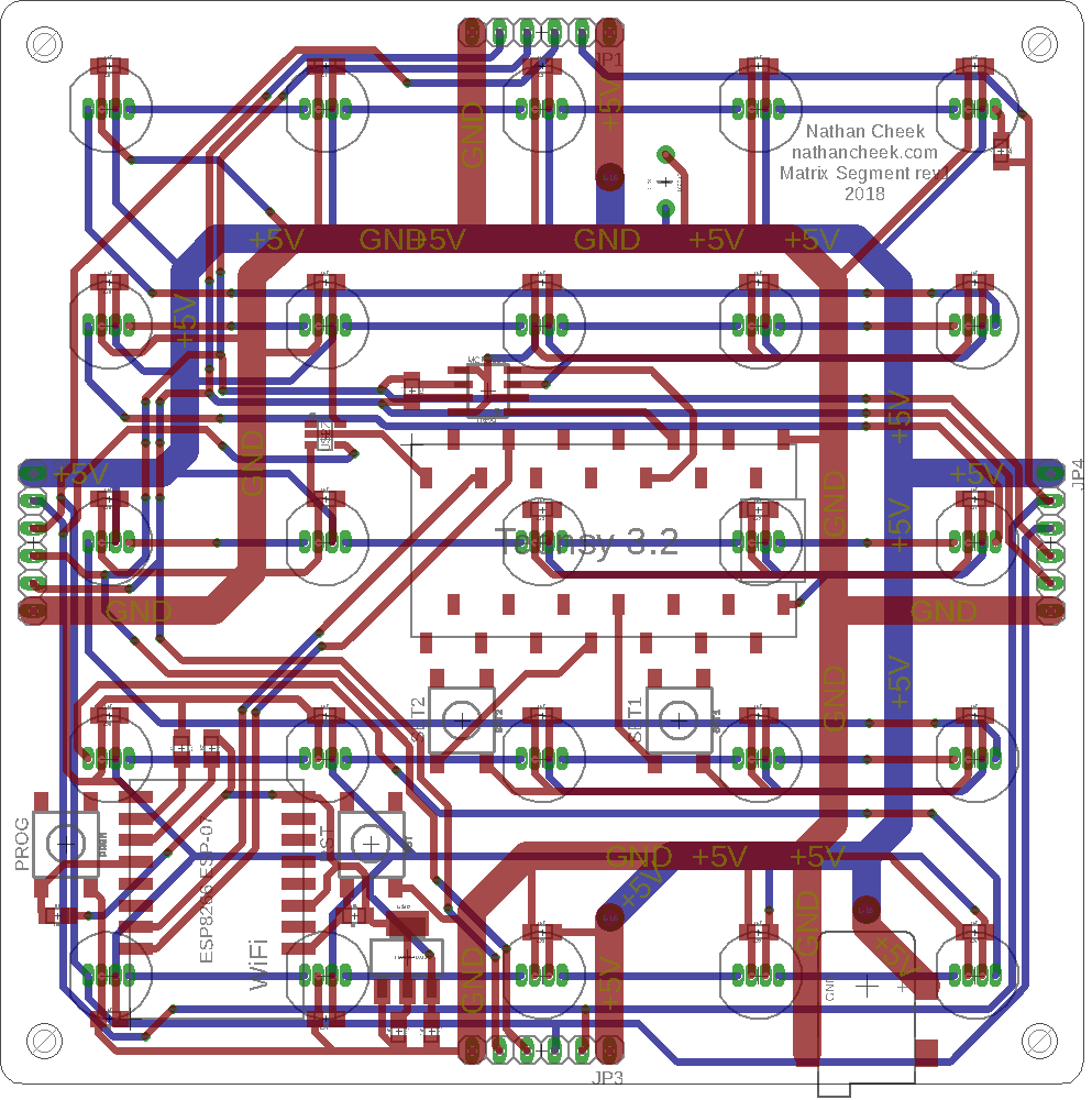
This design had two connector-related mistakes that I noticed once I began to assemble the boards. First, the SMD power jack was oriented to be pointing up into the board instead of out of the bottom of the board. This can be fixed by rotating that part 180º and rerouting the traces.
Second, I tried to design the connector layout such that they could plug in 1-to-1 without any wires having to swap between sides, but I made one critical mistake. The DIN pin from one board lines up with the DIN pin of another board, and the same happens with the DOUT pins. What should have happened was for DOUT to line up with DIN and vice versa. This is also a simple fix, requiring a small amount of trace rerouting.
These boards still work in spite of those two issues, but any future manufactured boards should have those problems fixed. I would also like to find a board-to-board connector to replace the current Molex KK 254 series connectors. This way multiple boards could be placed against each other without having wires running through them. I had trouble finding such a connector system for this first revision, but may continue researching.
Board Size
For my next revision I would like to revisit the idea of making a much larger PCB. I don’t remember how much a 200x200mm board cost back when I decided to stick with the 100x100mm size, but I suspect the prices have fallen. Currently from JLCPCB (as of 2019-06-02), it costs $17.40 for 5x boards sized at 200x200mm.
Calculating the current rate for 200x200mm boards, we get $17.40 / (20cm * 20cm * 5) = $.0087/cm^2. Compare this with the rate for 100x100mm boards $5.00 / (10cm * 10cm * 10) = $.005/cm^2 and we see that it is still 74% more expensive to go with the larger boards.
However, since I made this board last year, JLCPCB has removed the $15.00 non-standard soldermask color fee that I paid for my 100x100mm boards. It would actually be cheaper to get 5x 200x200mm boards with black soldermask now than it was to get 10x 100x100mm black PCBs last year. It might even be slightly cheaper overall to switch to larger boards when we consider the cost of the Molex connectors this design uses, since larger boards would need much fewer interconnects than the smaller boards.
Worrying about these board costs might not be worthwhile though. Looking at the $20+ DHL shipping costs as well as the LED cost of approximately $15 per 100 LEDs, we see that the boards make up only a small portion of the overall cost.
Other Hardware Changes
There are a few hardware changes that could be beneficial to a future board revision. First, there’s currently not a good way to keep a computer from powering the LEDs when programming the Teensy, other than removing the Teensy from the board. It may be good to add a diode to prevent the USB port from powering these LEDs.
Second, adding an RTC battery to the Teensy would allow us to use this display as a clock.
Third, changing the data pin on the Teensy to an SPI pin would allow us to use DMA to more efficiently control the LEDs.
Finally, adding slightly more space between the LED pads would greatly ease the soldering process.
Wireless Communications
I need to test whether the ESP8266 works as configured on the board. I haven’t had a need to use the ESP8266 functionality, but it needs to be tested before manufacturing more boards.
Supporting Software
None of this hardware design is very useful without accompanying software. Fortunately there is a lot of Neopixel software which is more or less compatible with this hardware (example), but I would like to create more programs specifically for this project. One goal is to have a decorative display of smooth patterns generated by the microcontroller.